
128K -> 256K
You allready have a 128K ram HP. Let's go for 256K!
You have to solder the second chip above the first. Warning: It's a hard work... Usually, the pins are a little too short to manage an easy soldering.
You have to solder these pins together with the help of a tiny
piece of wire...
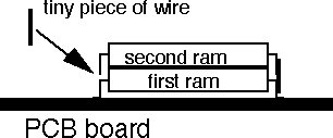
All the pins have to be soldered on the first RAM except 3 of them: You have to bend up pins # 22, 24 and 30. They have
to be connected to some signals present at the place where the
card connector is usually soldered.
Take a look at the layout of the card connector and also at the pinout of the rams.
The pins 2,21,37,38 and 39 of the card connector are devided
for the two card slots. For all those pins you have to use only
the part of that pins that has more distance from the battery
case. This is the part for card slot 1.
 pin 22:  connect it to pin 40 of the connector
 pin 24:     "            " 22           "
 pin 30:     "            " 21           "
There's some additionnal connections to do :
- Solder a 1Mohm resistance between pin 2 of the connector and Vcc
(you can find Vcc at the black condo, or at pin 32 of the ram
chips).
- Connect pin 39 and 40 of the connector together.
- Connect pin 37, 38 and 1 of the connector together.
- Don't forget the 74HC00 SMD under the black condo (on the left
of the next picture). The first pin of the 74HC00 is pointing
towards the screen (opposite direction as the ram). There's a
dot on the PCB near the pin #1.
Here's the result:  the same picture at high resolution (232k)
Put now some adhesive tape on the metal shield to prevent shortcuts
when you'll close the HP. Close the HP, and ready for the first
test!